
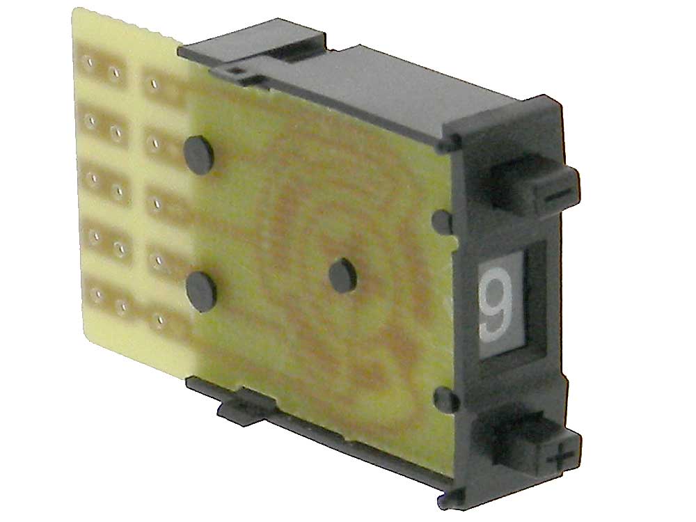
Last time we started to look into digital electronics. One handy building block for our experiments is the facility to provide input values to our circuits. An easy way to do is by using DIP switches but I find it always difficult to toggle the positions of the switches. Also, sometimes we want to provide a number of combinations to our circuit. A method to do this is by using a BCD switch like the below.
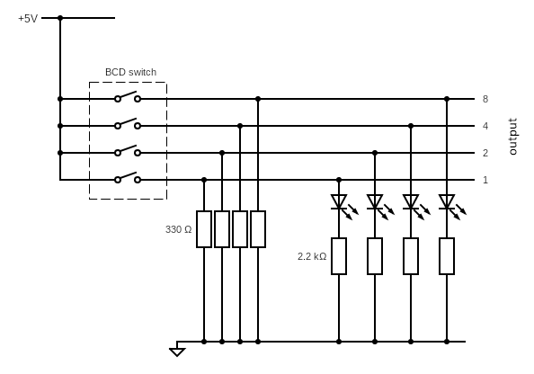
I plan to make an enclosure and display the BCD value using LEDs. As such, I need a pull-down resistor setup for my switch so that I can switch on my LEDs. The final schematic looks like the diagram below.
I built and tested the pull-down resistor in my lab and below is a photo of my setup.
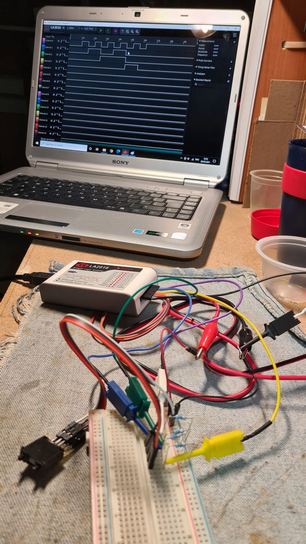
I connected the output from my BCD switch to my logic analyzer. I used the first four channels to display the values as I pressed the up button on my BCD switch. The figure below zooms on the logic analyzer screen shown in the photo above as I rotated the switch from 0 to 9.
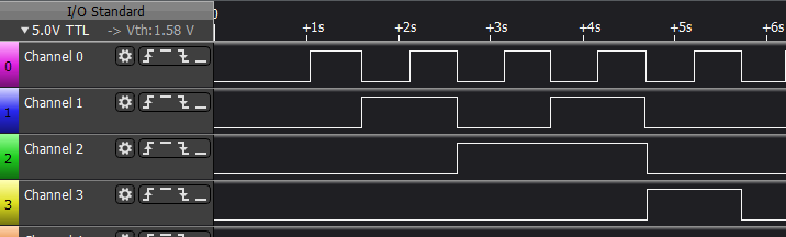
As I rotated the BCD switch, the following table was being created:
| Decimal Value | Channel 3 (MSB) | Channel 2 | Channel 1 | Channel 0 (LSB) |
|---|---|---|---|---|
| 0 | 0 | 0 | 0 | 0 |
| 1 | 0 | 0 | 0 | 1 |
| 2 | 0 | 0 | 1 | 0 |
| 3 | 0 | 0 | 1 | 1 |
| 4 | 0 | 1 | 0 | 0 |
| 5 | 0 | 1 | 0 | 1 |
| 6 | 0 | 1 | 1 | 0 |
| 7 | 0 | 1 | 1 | 1 |
| 8 | 1 | 0 | 0 | 0 |
| 9 | 1 | 0 | 0 | 1 |
I’ve also prepared the circuit on tinkercad so that you can see it in simulation. Unfortunately, there is no BCD switch so I had to opt for a DIP switch (I don’t have the switch flipping issue here:)
I hope that you find this helpful and keep in tune for our next experiment.