
In our first blog about Digital Electronics, we are going to look how to set up our lab to do a basic experiment using NOT gate. This is by no means an extensive tutorial, but a practical session that can help you get started in your new hobby.
The Power Source
Let us dive into it. For our labs we are going to use +5V to be the binary value of 1 and 0V to stand for the binary value 0. These are the common voltages for TTL circuitry (TTL stands for Transistor-Transistor Logic).
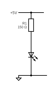
To start off, we need to set our power supply to +5V dc and connect its terminals to our breadboard. We will connect an LED to our input to signal the presence of voltage across our circuitry.
The LED setup is simple, we need an LED and a series resistor across our input voltage. But what value should our resistor be? From my LED specification sheet I know that it requires 20mA and has a potential difference (p.d.) of 2V to light up. Thus, my resistor must have a p.d. of 3V (5V – 2V from LED) at 20mA, that is, has a resistance of 3V/20mA = 150ohms.
The NOT gate
Now, that we have our source ready, let us do a simple NOT binary operation (invertor). We will use the 7404 TTL IC for our logic gate.
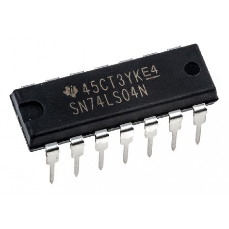
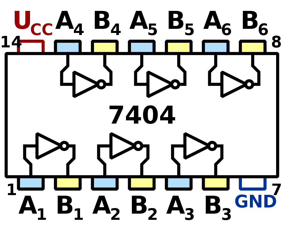
7404 hex-invertor photo and pin out
The truth table for an invertor is simple:
| Input (A) | Output (B) |
|---|---|
| 0 | 1 |
| 1 | 0 |
We will set up a simple circuit to show this in practice. The diagram below shows my setup.
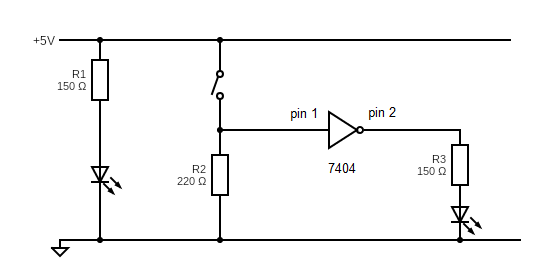
I am using a pull-down setup for my input switch. Once the switch is closed it will supply 5V (binary 1) to pin 1 of the NOT gate and when it is open it will have few mV (binary 0).
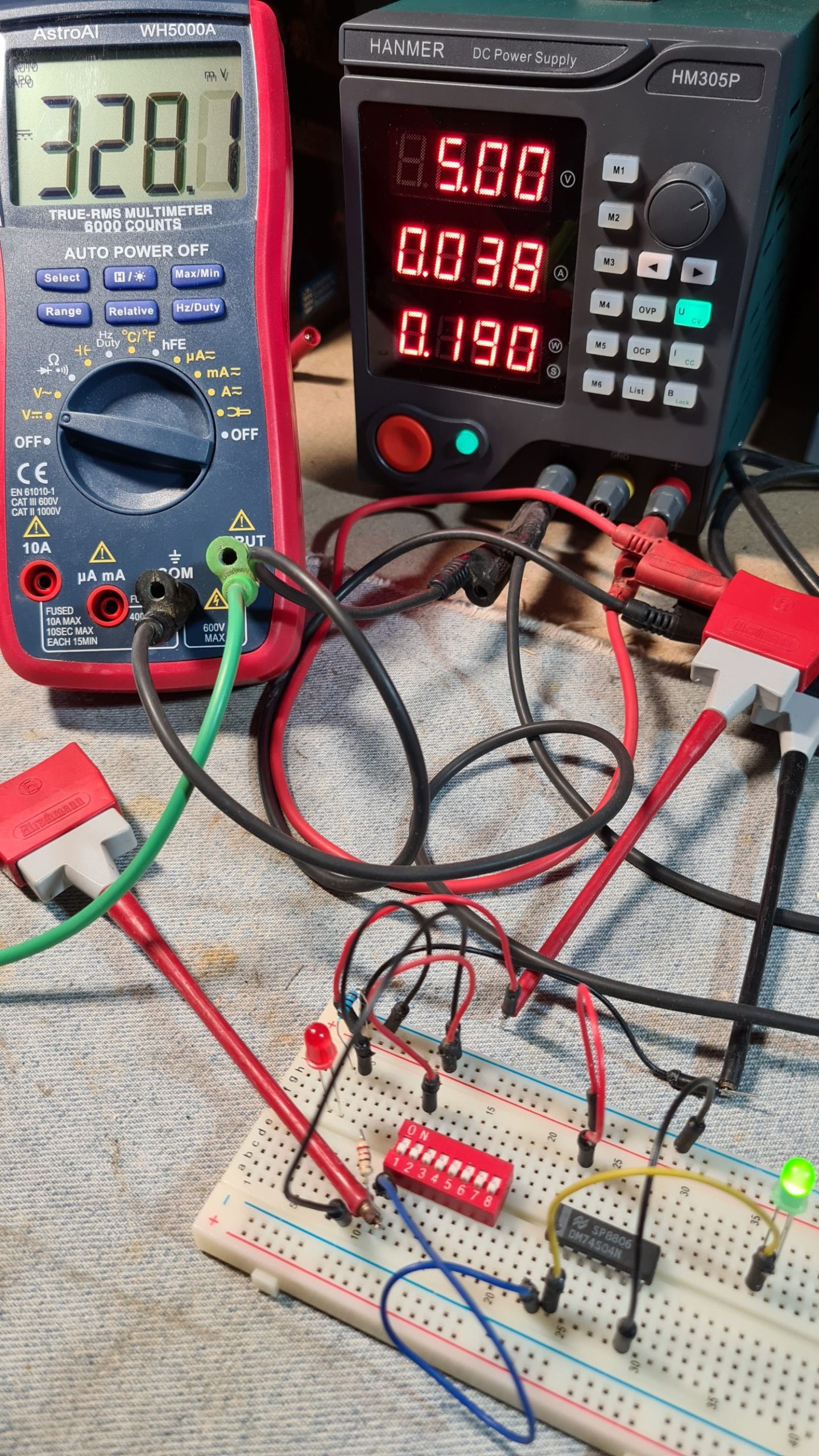
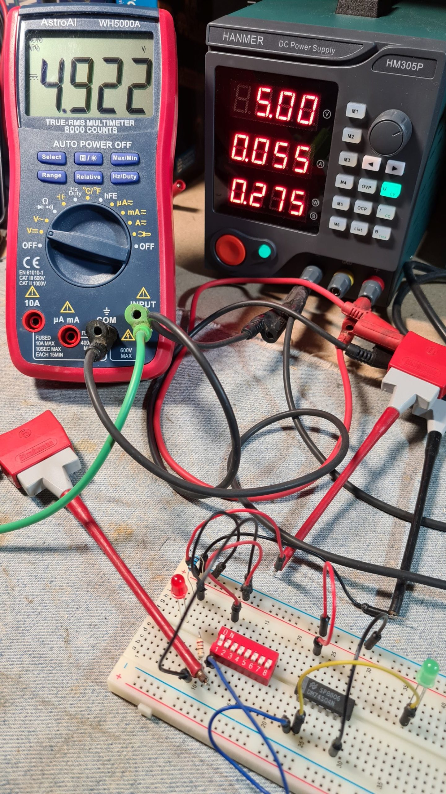
Here are some pictures from my experiment. The first one is when the switch (switch 1) is open and the LED is on; that is, I am supplying a 0 to the input and I get a 1 for the output. The second photo is when the switch is closed. As one can see from the multimeter, the input voltage on pin 1 of my 7404 is 5V and thus I am setting the input value to 1. As a result, the green LED is off; that is, as I give the NOT gate an input of 1, it gives me 0.
I hope that this gets you started in doing more experiments using logic gates. Next time, we will do some more exciting experiments, such as testing De Morgan’s theorem in practice!